Electronics Projects
Arduino – Basic Program Structure
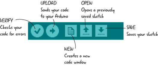
Arduino – Program Structure
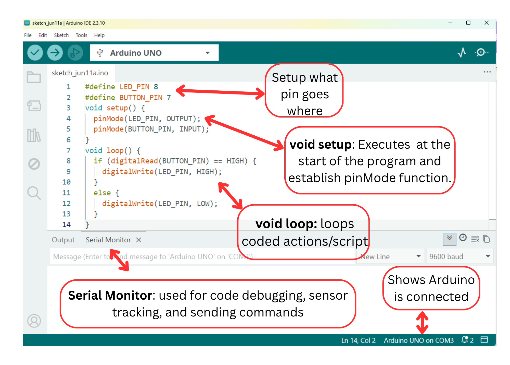
void setup() – This function executes only once at the beginning of the program. This function executes only once in the beginning. Here we define the mode of a particular pin like pinMode(LED_BUILTIN, OUTPUT), the initialization of serial communication or a library. The “void” indicates that nothing is returned on execution.
void loop() – It is the main program loop that runs continuously after the “setup” function has been executed. This function executes the core logic of the program, it runs over and over again.
Comment
You can add single-line comments to your code using double slashes (//) and block comments, or multi-line comments using /*… */. Comments are ignored by the compiler and do not affect the execution of the program. They are used after a valid statement to provide more information about the purpose or functionality of specific code segments or to provide a future reminder.
// this is a single line comment
/* this is an enclosed block comment don’t forget the closing comment – they have to be balanced! */
Spaces, tabs, and line breaks are used for code formatting to improve readability and organization.
Curly braces {}
Curly braces (also referred to as just “braces” or “curly braces”) define the beginning and end of function blocks and statement blocks such as the void loop() function and the for and if statements. An opening curly brace ‘{‘ must always be followed by a closing curly brace ‘}’. If we don’t put ‘}’, it can often lead to compiler errors that can sometimes be hard to track down in a large program.
Semicolon
A semicolon is used to end a statement and separate elements of the program. Note* It’s important to include the semicolon at the end of each statement in Arduino programming, as omitting it can result in compilation errors.
Variables
A variable is a way of naming and storing a numerical value for later use by the program. Variables can be numbers that can be continually changed as opposed to constants whose value never changes. Also variable can be a character value or any String. A variable need to be declared and optionally assigned to the value needing to be stored.
Constants: In Arduino, you can also define constants, which are variables whose value cannot be changed once set. Constants are typically declared using the const keyword. For example:
Data Types
Arduino supports several data types, including:
- int: Used to store integer values (whole numbers).
- float: Used to store floating-point values (decimal numbers).
- char: Used to store single characters.
- boolean: Used to store either true or false values.
- string: Used to store a sequence of characters.
Functions
A function is a block of code that has a name and a block of statements that are executed when the function is called. They allow you to organize your code into modular and reusable components.
Digital Input/Output
They are used to interface with external devices and sensors. Digital inputs are used to read the state of a digital signal, which can be either HIGH (5V) or LOW (0V). The Arduino board has several digital pins that can be configured as inputs using the pinMode() function. Digital outputs are used to send a digital signal, either HIGH or LOW, to control external devices such as LEDs, motors, or relays.
Analog Input/Output (I/O)
Analog inputs are used to read continuous analog signals from sensors, such as light sensors, temperature sensors, or potentiometers. Arduino boards typically have 6 analog input pins, which are represented by numbers A0, A1, A2, A3, A4, A5.
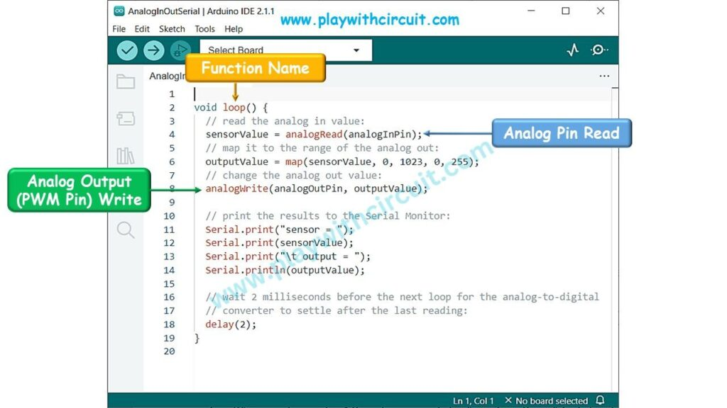
Analog inputs are read using the analogRead() function, which returns a value between 0 and 1023 representing the voltage level.
Analog outputs (PWM – Pulse Width Modulation) allow you to simulate an analog voltage by rapidly switching a digital signal ON and OFF. This is useful for controlling devices like servo motors or dimming LEDs. Arduino boards have several digital pins capable of analog output, denoted with a tilde (~) symbol. The analogWrite() function is used to set the analog output value.
Libraries
Arduino provides libraries that contain pre-written code to simplify complex tasks. Libraries extend the functionality of Arduino by providing additional functions and features. They contain functions, constants, and classes that can be used to extend the capabilities of the Arduino board.
Basic Arduino and Parts
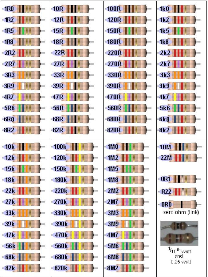
Resistors
A resistor is an electrical component used to create resistance in the flow of an electrical current. The amount of resistance a resistor has is measured in ohms. Resistors are important as supply too much voltage to a component you can completely destroy it. Resistors can be used to prevent this with just a little bit of math.
To make calculations easier, I have linked 2 tools to help you calculate exactly what you need and what you have.
https://ohmslawcalculator.com/ohms-law-calculator
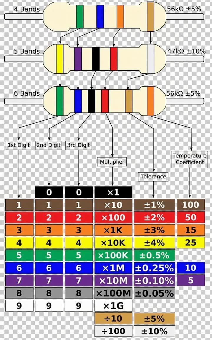
Read the color bands from left to right. The colors on the first 2 or 3 bands correspond to numbers from 0 to 9, which represent the significant digits of the resistor's ohmic value. The last band gives the multiplier. For example, a resistor with brown, green and green bands is rated at 15 mega-ohms (15,000,000 ohms). The code is as follows:[2]
- Black: 0 significant digit, multiplier of 1
- Brown: 1 significant digit, multiplier of 10
- Red: 2 significant digit, multiplier of 100
- Orange: 3 significant digit, multiplier of 1,000 (kilo)
- Yellow: 4 significant digit, multiplier of 10,000 (10 kilo)
- Green: 5 significant digit, multiplier of 100,000 (mega)
- Blue: 6 significant digit, multiplier of 1,000,000 (10 mega)
- Violet: 7 significant digit
- Gray: 8 significant digit
- White: 9 significant digit
- Gold: multiplier of 1/10
- Silver: multiplier of 1/100
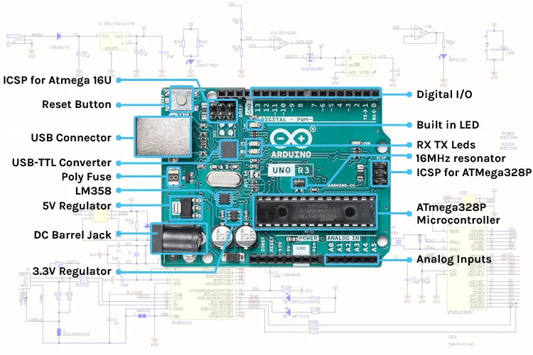
Arduino Board and Parts
Arduino Board
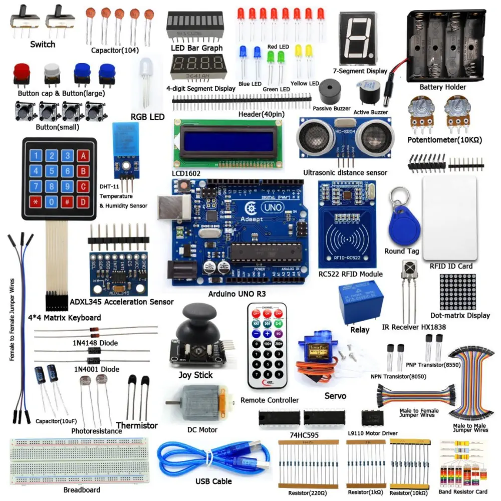
Parts
Sample Projects
Arduino - LED - Blink | Arduino Tutorial (arduinogetstarted.com)
Arduino - RGB LED | Arduino Tutorial (arduinogetstarted.com)
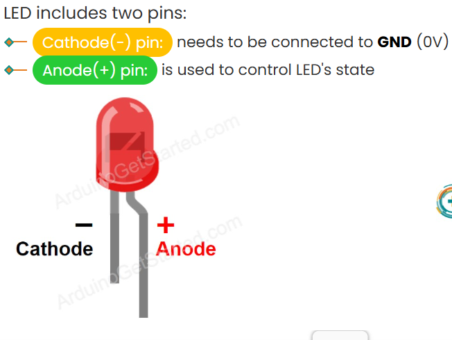
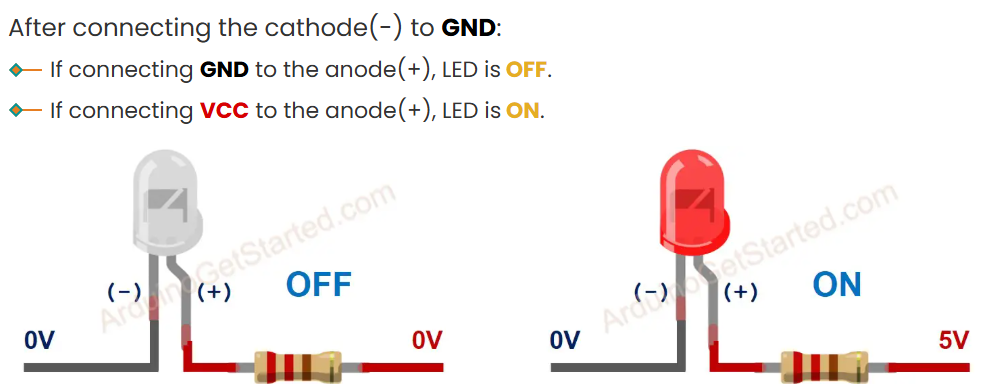
LED
LED

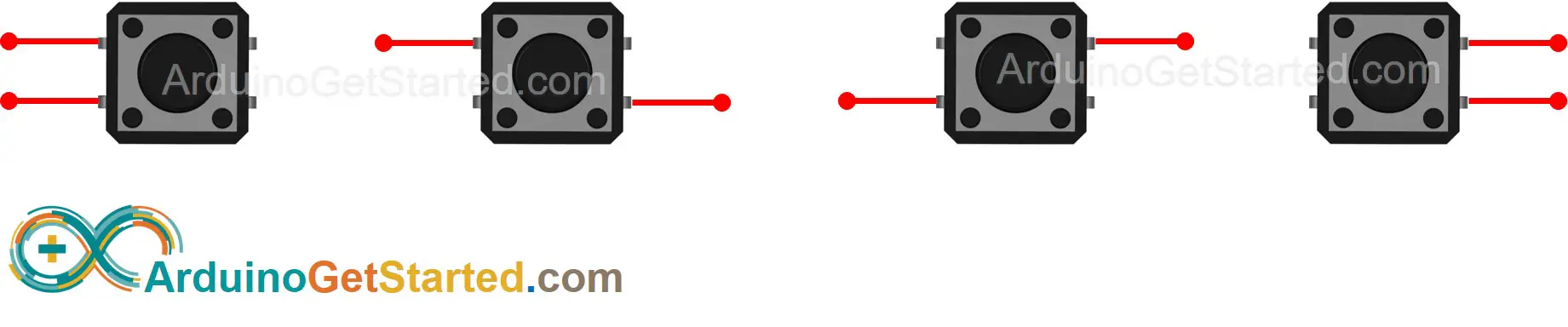
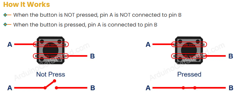
Push Buttons
Push Buttons

There are four ways (actually two because of symmetry) to connect to buttons. You can only use two at a time:
Beginner Arduino Projects
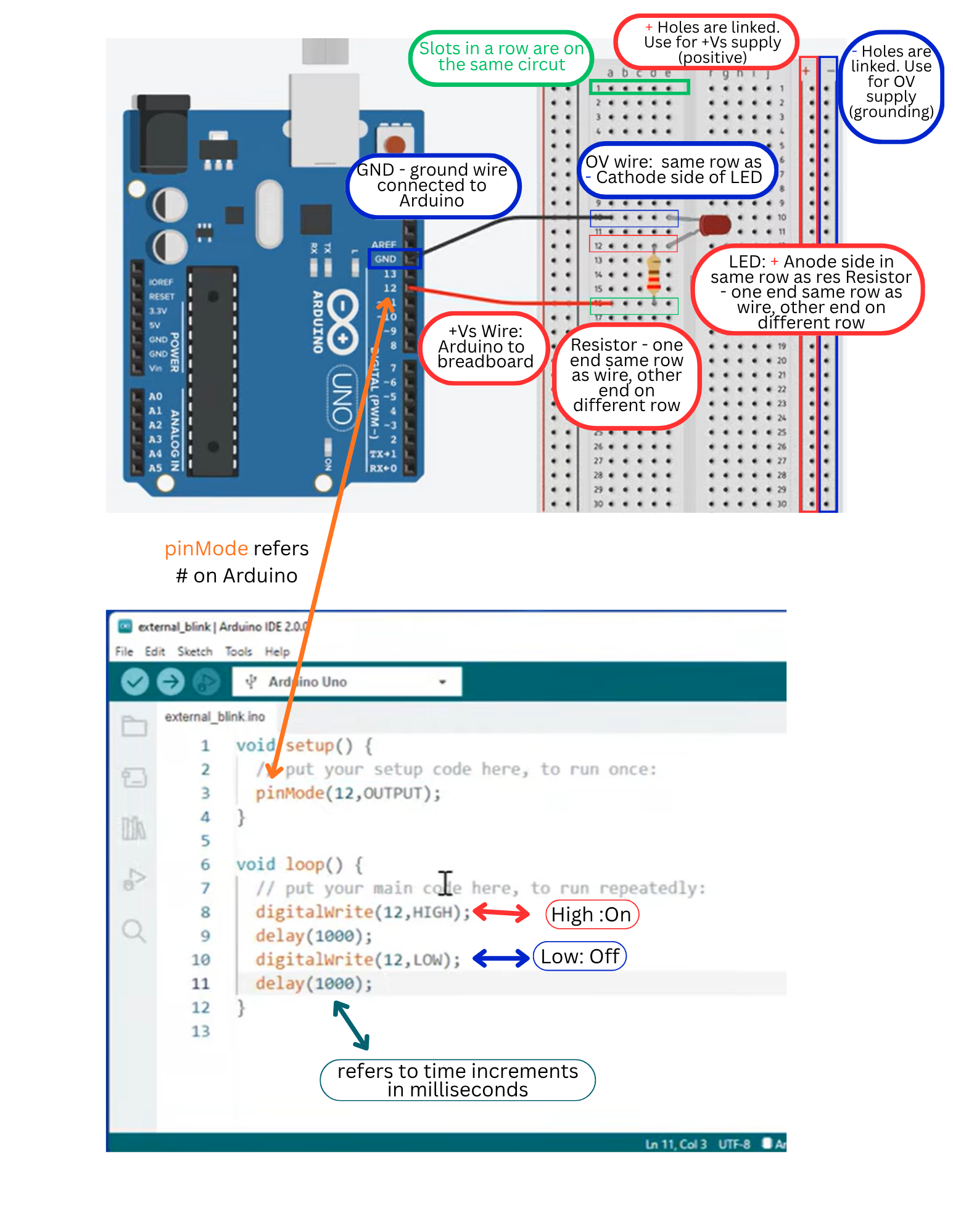
1. Arduino - LED - Blink
Equipment
- 1x Arduino Uno
- 1x USB 2.0 cable type A/B (for USB-A PC)
- 1x USB 2.0 cable type C/B (for USB-C PC)
- 1x LED Kit
- 1x LED red
- 1x LED module
- 1x 220Ω Resistor
- 1x breadboard
- 1x Jumper wires
LED Functions

Project Set-up
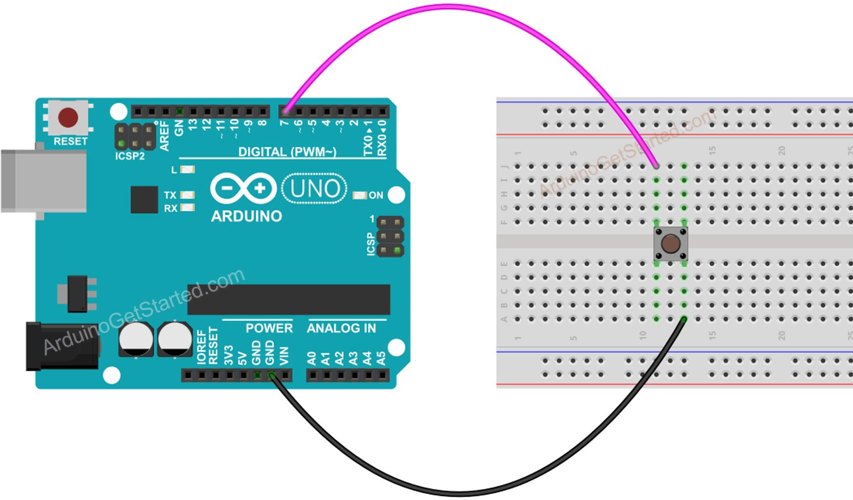
2. Arduino - Button
Equipment:
- 1x Arduino Uno
- 1x USB 2.0 cable type A/B (for USB-A PC)
- 1x USB 2.0 cable type C/B (for USB-C PC)
- 1x Breadboard-mount Button w/ cap
- 1x Breadboard-mount Button Kit
- 1x Panel-mount Button
- 1x Push Button Module
- 1x breadboard
- 1x Jumper wires
Buttons
Project Set-up
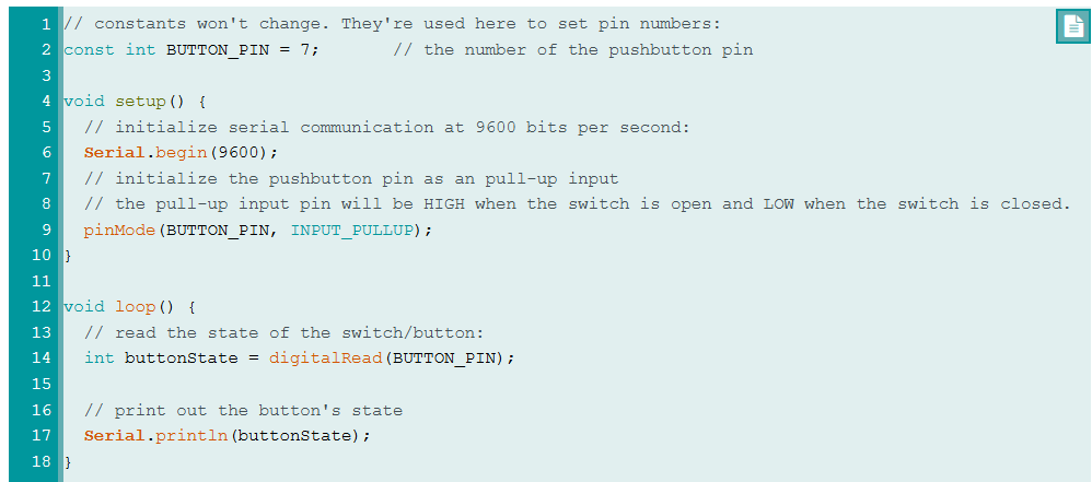
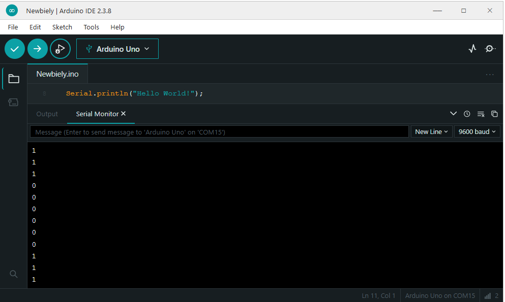
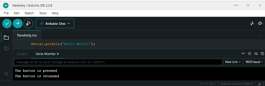
Testing your script
Open Serial Monitor (under Tools). Press button a few times and the script should change between 0 and 1 (1 is high, 2 is low).
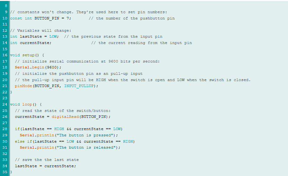
Modify the code to detect the press and release events:
3. Arduino - Turn LED ON and OFF With Button
Turn LED ON and OFF With Button Tutorial
Equipment
- 1x Arduino Uno
- 1x USB 2.0 cable type A/B (for USB-A PC)
- 1x USB 2.0 cable type C/B (for USB-C PC)
- 1x Push Button
- 1x Push Button Module
- 1x breadboard
- 6x Jumper wires
- 1x LED
- 1x 220 Ohm resistor
- 1x 10k Ohm resistor
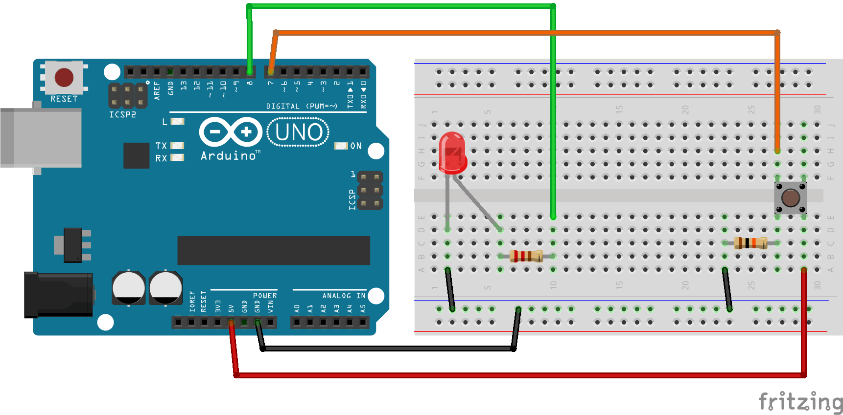
Project Set-up
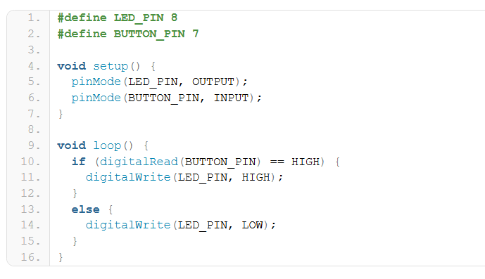
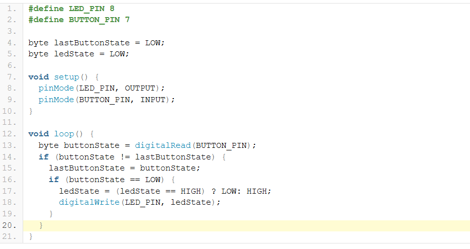
Code to turn light on when button is held:
Code to turn button on and off LED with button:
Soldering
Warning: Soldering involves extreme heat, toxic fumes, and sometimes heavy metals like lead. The most critical safety measures are wearing safety glasses to protect your eyes from sputtering solder, using ventilation or a Solder Fume Extractor to avoid breathing in flux smoke, and washing your hands thoroughly with soap after every session.
Soldering Equipment
Equipment
- Soldering station/tips
- Solder
- Tip cleaner (cleaning ball or sponge)
- Flux
- Solder wick
- Something to hold your project in place
- Flush cutters
- Fume mitigation
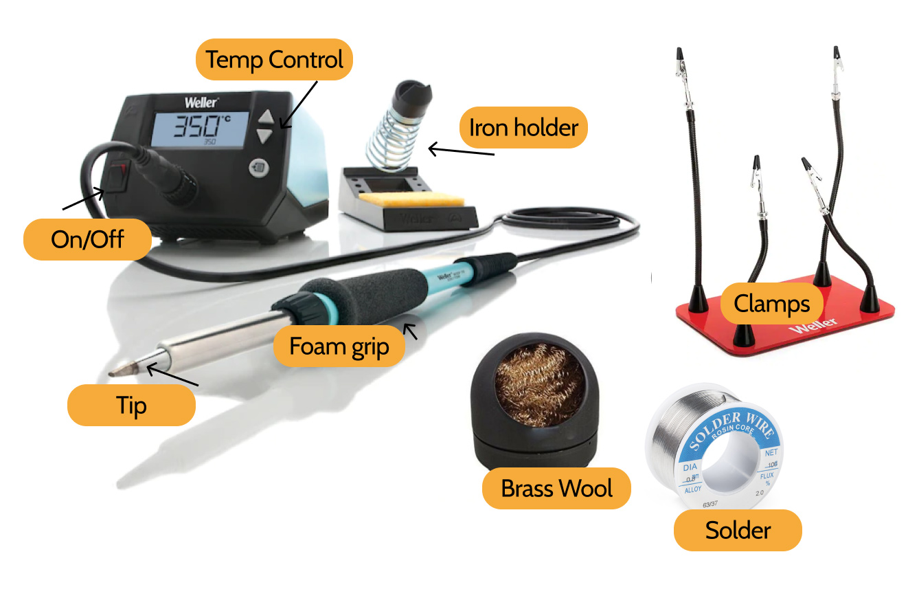
Soldering Irons and Soldering Stations
A soldering iron is the fundamental piece of handheld equipment used in the process of soldering. Soldering irons heat up to melt solder around electrical or mechanical connections; as it melts, solder flows into the spaces between and around two components. Once bonded, the solder is left to cool and harden, creating a permanent and conductive join; it can melt back into liquid form by reheating enough the join. The process of reheating and separating a previously soldered joint is called desoldering.
Brass and Conventional Sponges
Use either a wet sponge or a brass sponge to remove debris from the tip of the soldering iron. This will help keep soldering iron tips clean by removing oxidation (oxidated tips will get black and not accept solder). Brass sponges removes debris in tips better; they have a smaller thermal shock and they don't need water as conventional sponges.
Solder
Solder is a metal alloy that melts to create a permanent bond between electrical parts or components. Solder comes in both lead and lead-free presentations, also in different diameters; the most common diameters used are 0.8mm and 1.5mm. Inside the solder core a material known as flux helps improve electrical contact and mechanical strength of solder.
Helping Hands/Clamps
A helping hand/clamps, also called "third hand," is a device that can assist you while soldering by holding the parts or components you are trying to solder, leaving your hands free to work.
Soldering 101
Warning: Always wearing safety glasses to protect your eyes from sputtering solder.
Warning: Soldering involves extreme heat. The soldering tip can reach over 700°F. Alway secure the iron in it's holder when not in use. Never touch the tip or place the iron directly on the table or work bench. Remove all flammables from work area.
Warning: Melting solder creates visible smoke. Breathing fumes from soldering can cause eye, throat, and lung irritation. Always work in a well-ventilated area or use a benchtop solder fume extractor.
Warning: Some solder contains lead, which can be harmful if ingested. Lead particles can be transferred from hands to your mouth if eating, drinking, or touching your face. Never eat or drink while handling solder and always wash your hands with soap when done.
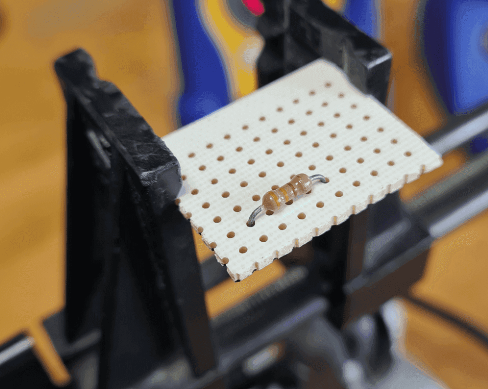
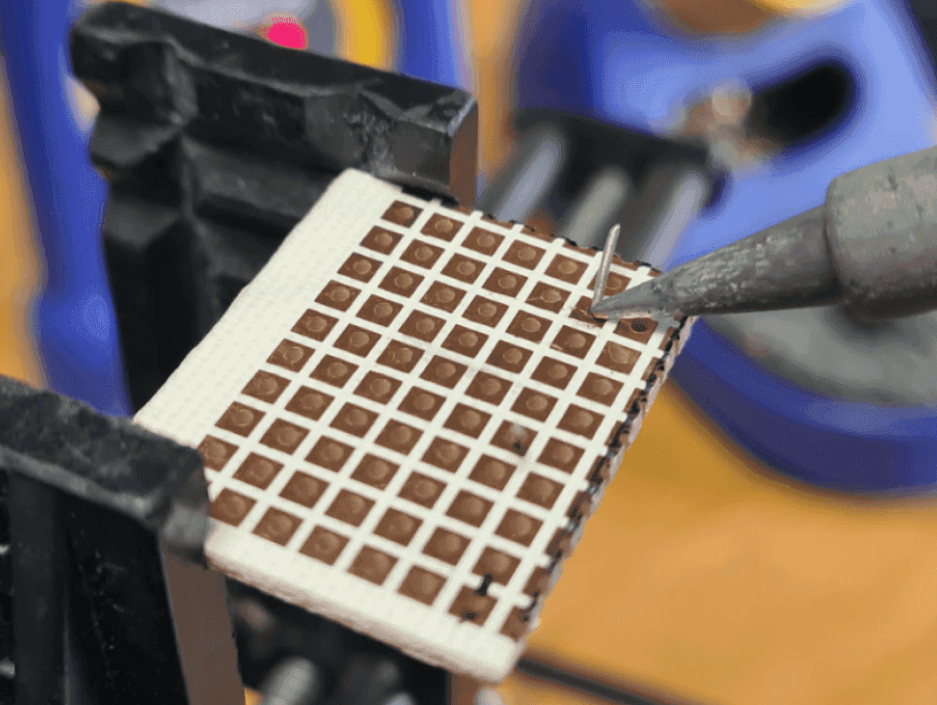
Prepare your circuit boards (example)
- Use helping hands/clamps to secure your circuit board.
- Mount your resistor to the circuit board.
Prepare your soldering iron: Tinning
Tinning improves heat transfer from the iron to the electrical part and helps protect against oxidation.
- Heat the soldering iron to 400° C (or 752° F).
- Clean the soldering tip by wiping it agains a conventional wet sponge or a brass sponge. After cleaning the soldering tip, we should wait a few seconds to let the soldering tip heat up again.
- Touch the solder with the soldering iron tip, apply a small amount of solder on the soldering tip making sure the solder flows evenly around it.
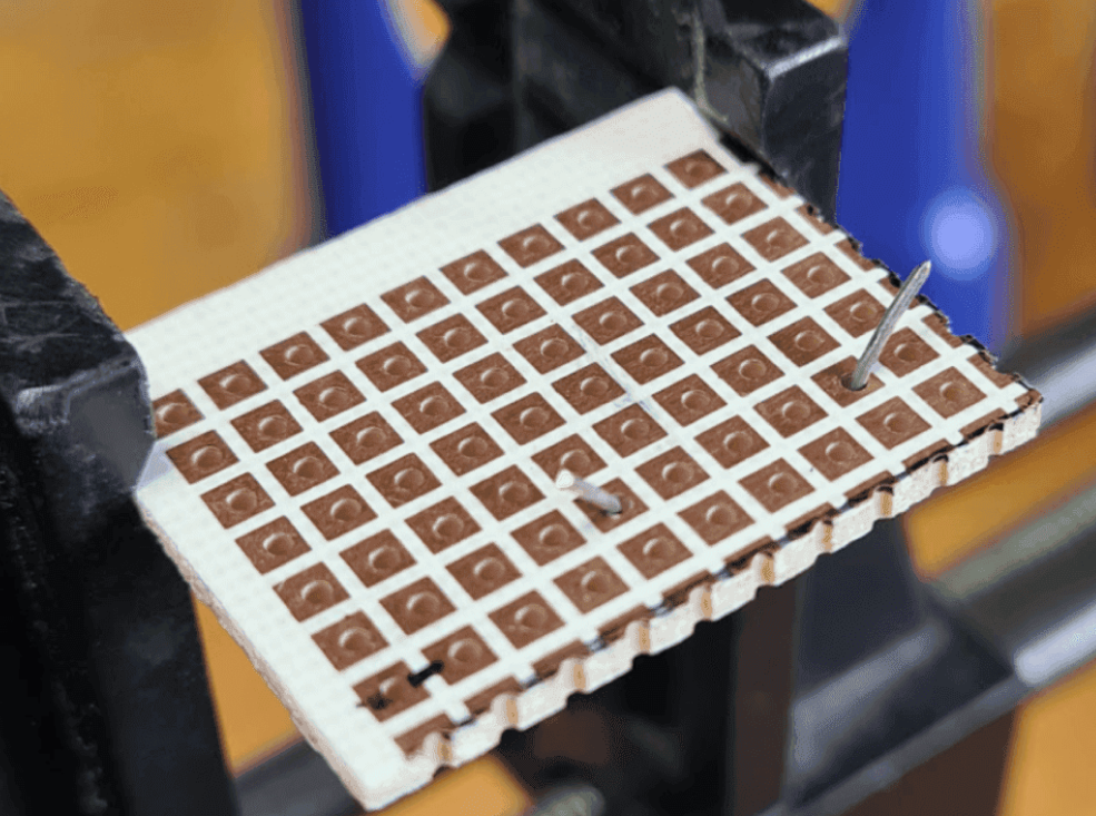
4. Flip the circuit board and bend it's leads outward 45°.
5. Touch the copper pad and one of the resistors leads simultaneously, hold the soldering iron in place to heat the joint formed by the pad and the resistor lead for three to four seconds.
6. Apply solder to the joint while holding the soldering iron on the copper pad and the resistor lead. Avoid applying solder directly to the soldering tip; the joint should be hot enough to melt the solder.
7. When there is enough solder in the joint, remove the soldering iron and let it cool down naturally. Once cool, snip the extra wire from the resistor lead. Do not blow on the joints to cool it down. Good solder joints are smooth, shiny, and have a volcano-like shape. Good solder joints also have enough solder to cover the entire joint but not too much to spill it.
Desoldering
To desolder a joint, we will need desoldering braid, also known as solder wick.
Using desoldering braid is simple:
- Place the desoldering braid on the top of the solder joint to remove.
- Heat the soldering braid and the solder joint with the tip of a soldering iron. Start removing the soldering braid; you will see that solder has been extracted and removed.
If you have a lot of solder, using desoldering braid may not be the best option. In this case, a device called solder sucker is a better option. A solder sucker is a handheld mechanical vacuum that sucks up hot solder, usually by pressing a button.
Using a solder sucker is also simple:
- Press the solder sucker plunger down.
- Heat the solder joint with the tip of a soldering iron, then place the tip of the solder sucker on top of the hot solder joint.
- Press the button of the solder sucker to suck solder.